New Products
See MoreBack in Stock
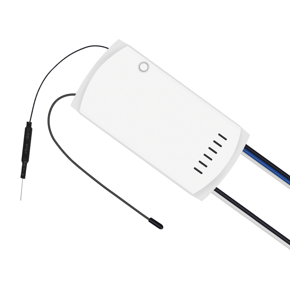
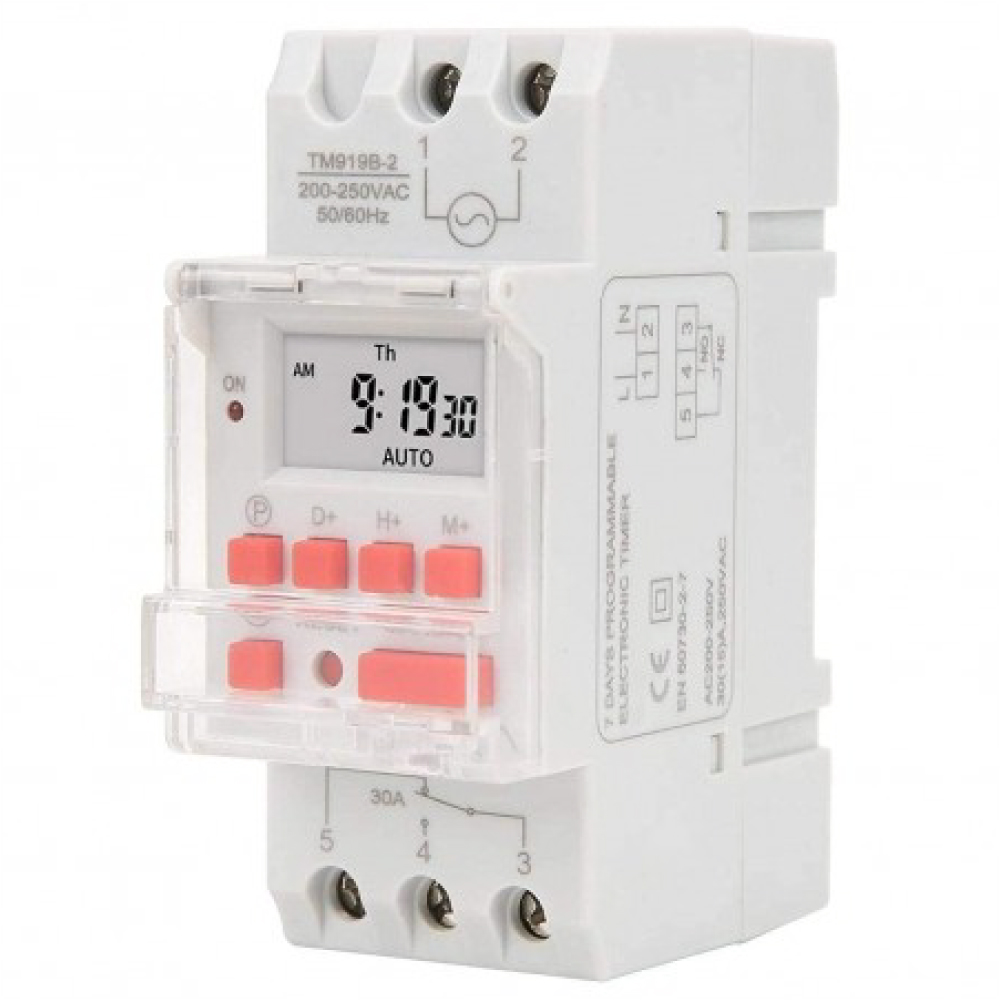
See MoreHome Automation
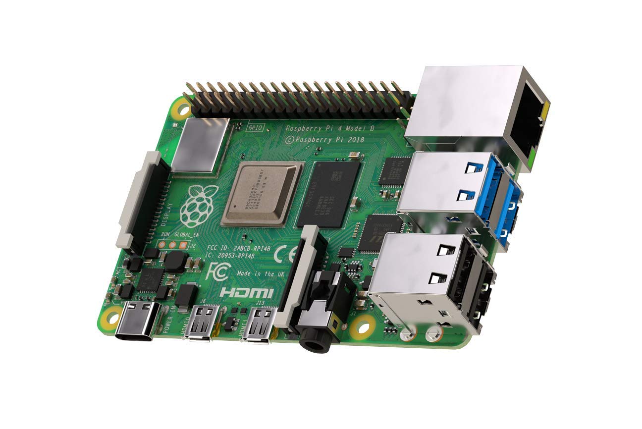
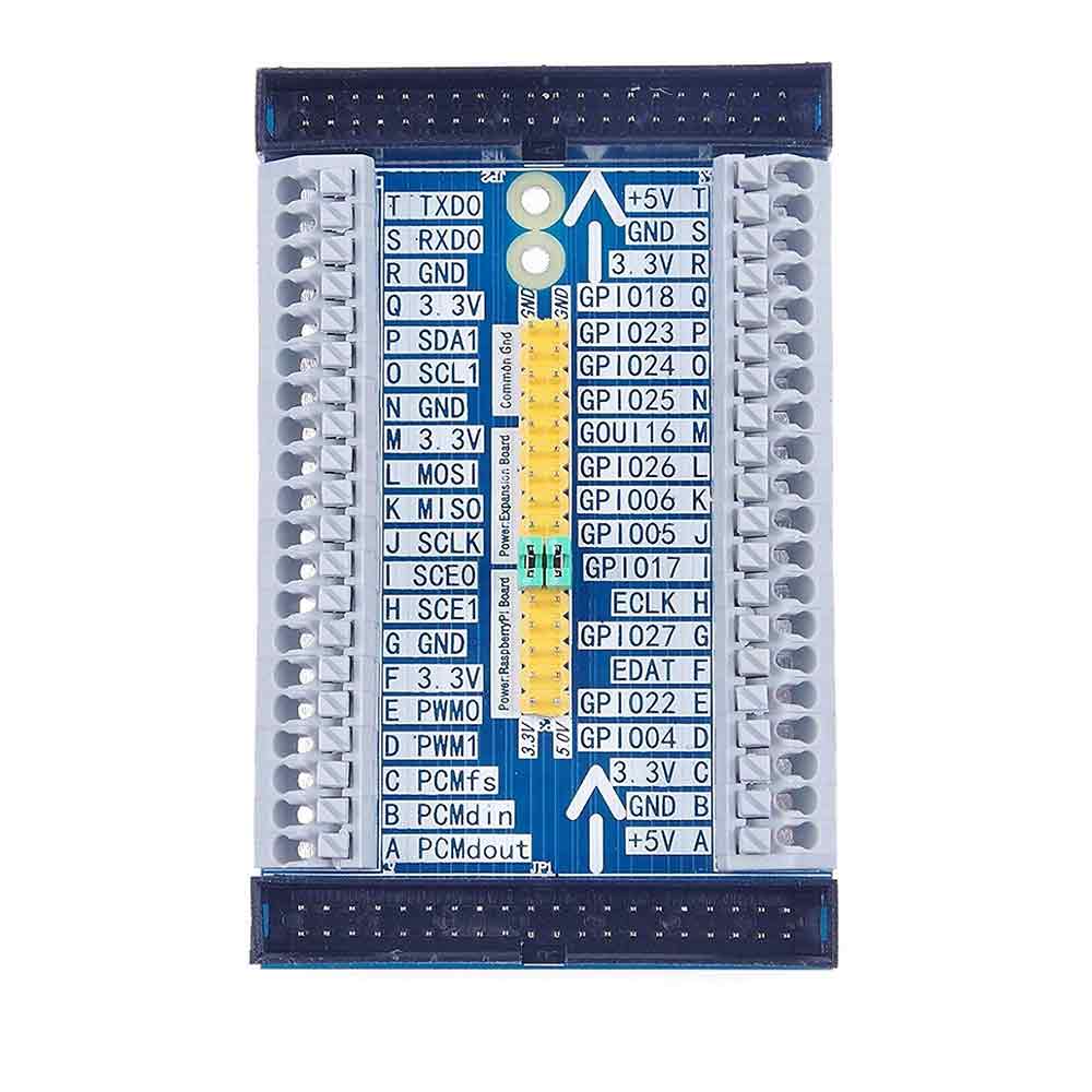
See MoreRASPBERRY PI & ACCESSORIES
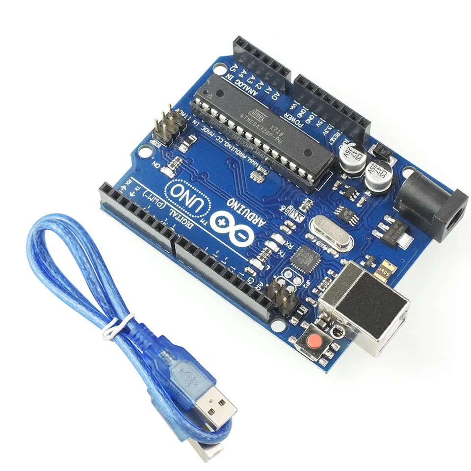
See MoreARDUINO & ACCESSORIES
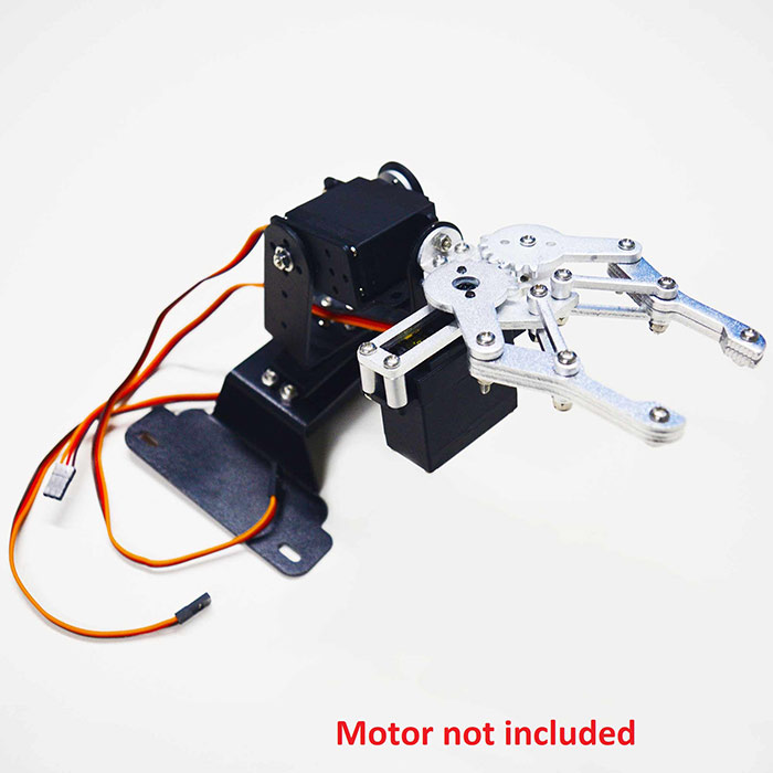
See MoreBasic Robotics
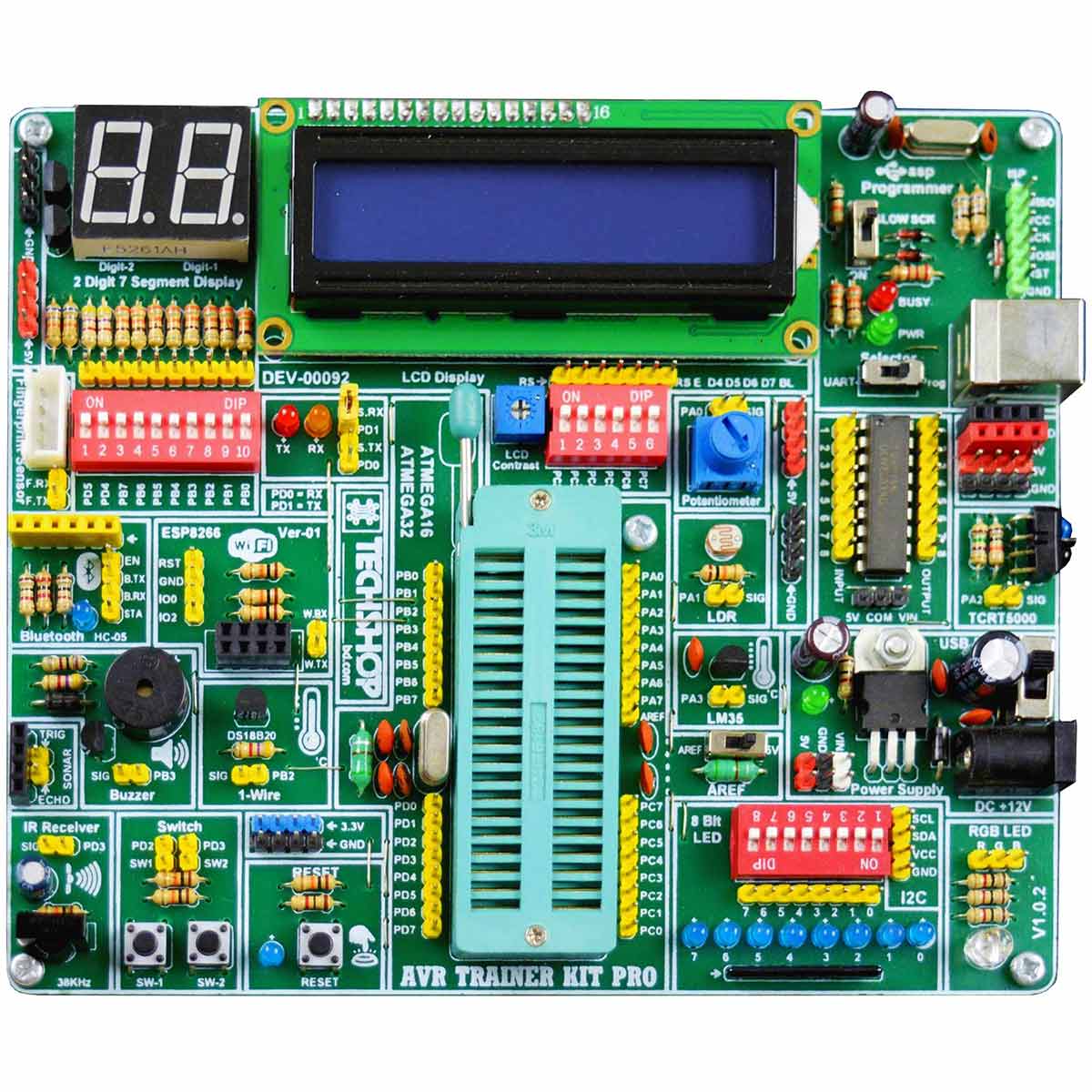
See MoreDeveloped by TechShop & Pi-LabsBD
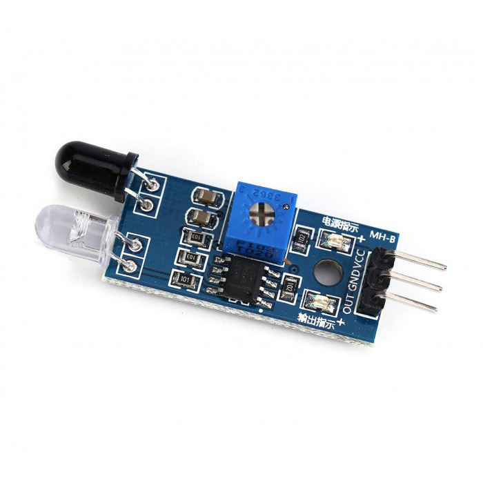
See MoreVARIOUS TYPES OF SENSOR
See MoreTools
See MoreOur Supplier

SparkFun, USA

Pi Labs, Bangladesh
Pololu, USA
Seeed Studio, China
DFRobot
Marketplace, Bangladesh
Hobbyking, Hong Kong

Techshop Bangladesh
Waveshare Electronics, China
.png)
Adafruit, USA
Help: 09678110110
09.00am - 08.00pm (7 days a week)
Pay cash on delivery
Pay cash at your doorstep
Service
All over Bangladesh
Warranty and Replacement
Up to 1 Year


.JPG)


.jpg)
_2.jpg)


.jpg)


.jpg)

01.jpg)


.jpg)


-01.jpg)